Capacity: 0.2Nm, 0.5Nm, 1Nm, 2Nm, 3Nm, 5Nm, 10Nm,20Nm, 30Nm, 40Nm, 50Nm,20Nm, 30Nm, 40Nm, 50Nm, 60Nm, 70Nm, 80Nm,100Nm, 200Nm,300Nm, 500Nm, 1000Nm, 2000Nm, 3000Nm
Specifications:
|
Torque accuracy
|
≤0.5% F·S
|
|
Repeatability
|
≤0.5%F·S
|
|
Hysteresis
|
≤0.5%F·S
|
|
Non-linearity
|
≤0.5%F·S
|
|
Overload
|
No overload capability
|
|
Insulation
|
≥200MΩ
|
|
Operating Temp. Range
|
-20~60℃
|
|
Relative humidity
|
≤90%RHr
|
|
Zero torque frequency output
|
10KHz Refer to《Calibration Certificate》
|
|
Forward torque full-scale frequency output
|
15KHz Refer to《Calibration Certificate》
|
|
Reverse torque full-scale frequency output
|
5KHz Refer to《Calibration Certificate》
|
|
Torque sensor signal output is frequency signal TTL amplitude
|
3.6-5V
|
|
Torque sensor speed inaccuracy without built-in encoder:
|
60 pulses/rev (no accumulation error)
|
|
Torque sensor speed inaccuracy with built-in encoder:
|
900 pulses/rev (no accumulation error)
|
Dimensions
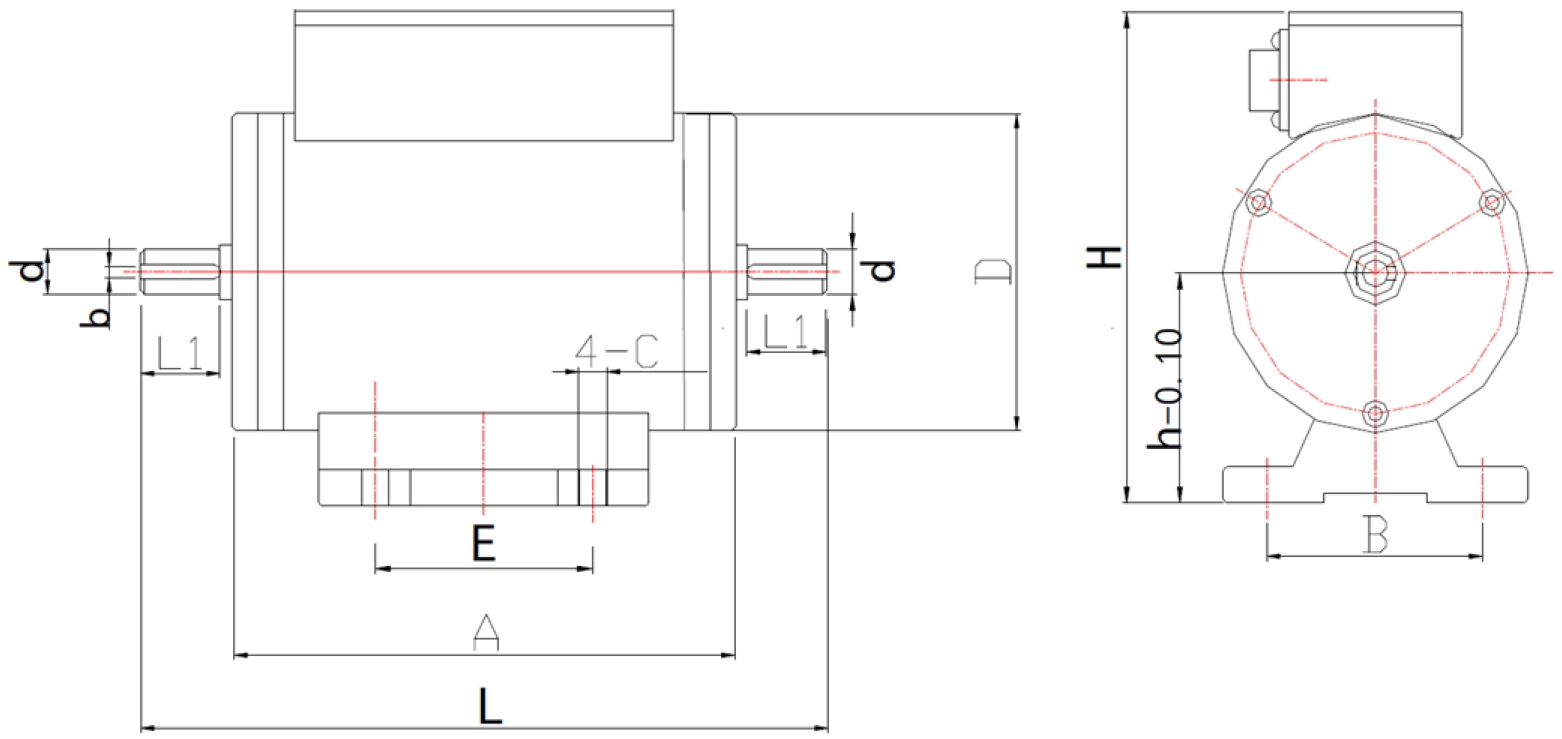
Dimensions(mm)
|
Nm
|
d
|
D
|
L
|
L1
|
A
|
E
|
b
|
c
|
h
|
H
|
B
|
Speed
|
|
10
|
Φ10h6
|
Φ70
|
158
|
18
|
118
|
50
|
3
|
4.5
|
51
|
107
|
50
|
12000-30000
|
|
50
|
Φ14h6
|
Φ70
|
176
|
25
|
120
|
50
|
5
|
4.5
|
51
|
107
|
50
|
12000-30000
|
|
100
|
Φ18h6
|
Φ75
|
210
|
30
|
142
|
72
|
6
|
6.5
|
58
|
117
|
62
|
10000-20000
|
|
200
|
Φ24h6
|
Φ85
|
242
|
42
|
150
|
72
|
8
|
6.5
|
63
|
127
|
62
|
10000-20000
|
|
300
|
Φ28h6
|
Φ90
|
242
|
42
|
152
|
72
|
8
|
6.5
|
63
|
130
|
62
|
8500-15000
|
|
500
|
Φ38h6
|
Φ100
|
272
|
56
|
154
|
72
|
10
|
6.5
|
69
|
140
|
62
|
7000-12000
|
|
1000
|
Φ48h6
|
Φ105
|
328
|
80
|
159
|
72
|
14
|
8.5
|
70
|
144
|
82
|
6000-11000
|
|
2000
|
Φ55h6
|
Φ125
|
385
|
105
|
167
|
72
|
16
|
8.5
|
74
|
162
|
82
|
5000-9000
|
|
3000
|
Φ65h6
|
Φ132
|
385
|
100
|
176
|
72
|
18
|
8.5
|
80
|
172
|
82
|
4200-8000
|
Among them:10Nm include:0.2Nm, 0.5Nm, 1Nm, 2Nm, 3Nm, 5Nm, 10Nm.
50Nm include:20Nm, 30Nm, 40Nm, 50Nm。
100Nm include:20Nm, 30Nm, 40Nm, 50Nm, 60Nm, 70Nm, 80Nm.
Torque sensor requirements for power supply
When the sensor uses the external power supply, the power supply voltage is: 9-36V, and the power supply is greater than 2W.
In a strong interference environment, such as power supply pollution, space electromagnetic radiation and other factors, resulting in the sensor can not work properly, consider the following measures:
1. Make sure the system is well grounded (including sensors, meters, other equipment) and try to experiment at different grounding points.
2. Separate transmission of signal transmission lines that may interfere with each other. When conditions permit, metal shielding tubes (net) can be added to achieve isolation and shielding.
Pay attention
1. Installation environment requirements: Temperature: -20 ° C ~ 60 ° C
Humidity: <90%RH
No flammable or explosive materials
2. Do not hit and collide the sensor directly during installation.
3. Do not operate live during installation.
4. This sensor is non-waterproof and non explosion-proof design. Please pay attention when using it.
5. Avoid strong interference and ensure the normal operation of the instrument.
6. The sensor can not be overloaded for a long time, and should avoid excessive impact load, otherwise the elastic shaft may be permanently deformed and cannot return to the measurement zero point.
7. In order to avoid electric shock, the three-core power cord should be connected to the three-wire power socket for power supply. The center ground of the three-wire power socket must be reliably grounded.
8. The online test cable should be properly secured to prevent the rotating system from twisting it.
9. The shielded wire joint at the aviation plug of the test cable should not be removed at will.
10. The aviation plug of the test cable and the air socket of the sensor and instrument should be tightened reliably.
Regular maintenance and maintenance
Before maintenance, please confirm that the power supply and sensor power supply have been cut off. Only professionally trained personnel can disassemble and repair.
Users can inspect the sensor periodically for half a year or one year according to the use requirements and environment. In addition to routine maintenance and maintenance, the inspection items should also be cleaned and lubricated.
Sensors must operate in accordance with the operating environment specified in the instructions. In addition, some unexpected situations may occur in operation. Users should do routine maintenance according to the following inspection contents, maintain good operating environment, and find out the causes of abnormalities early is the way to maintain the long-term operation of sensors.
1. Check whether the temperature and humidity of the operating environment meet the requirements of the specification.
2. Check the vibration of the sensor system and the temperature and noise of the bearing parts at both ends of the shell. Smooth operation, suitable temperature and humidity, no unusual noise.
3. Check whether the fasteners of the system are loose.
4. Check whether the power system voltage and the power supply voltage of the sensor are in the rated range.
According to the user's requirement environment, the sensor is checked periodically for half a year or one year.
In addition to routine maintenance, the bearings should also be cleaned and lubricated..