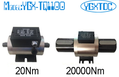
Model: YGX-TQ1100 Non-contact dynamic torque sensor
Overview
Torque sensor is developed on the basis of the strain bridge proprietary technology, specifically for measuring the torque, speed parameters of the sensor. This series of torque sensors using strain bridge electrical measurement technology, with a group of ring transformer non-contact to provide power supply, with micro-power signal coupler instead of the ring transformer for non-contact transmission signal, effectively overcome the inductance coupling signal to bring high Harmonic interference and energy ring transformer on the signal ring transformer mutual interference, while the output pulse into the square wave signal, therefore, this series of torque sensors can be a long time, high speed operation.
This series of torque sensors can be used for static or can be used for dynamic measurement, a variety of forms of installation design, to the user a great convenience.
Technical Features:
1. Can measure static torque, also can measure the rotating torque;
2. High precision, good stability, strong anti-interference;
3. Small size, light weight, easy to install;
4. No need to repeatedly zero to continuously measure the forward and reverse torque;
5. No wear ring and other wear parts, you can run high speed long time;
6. Strain elastomer strength, can withstand 150% load;
7. Strong anti-interference, can be any position, any direction to install;
8. The sensor part can be used independently from the secondary instrument, directly with the measurement board, PLC or DCS composition of the torque measurement device
Torque working principle
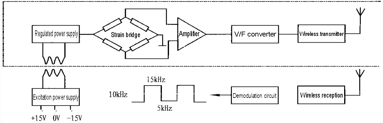
As shown above diagram, the strain bridge is powered by a set of toroidal transformers provided on the sensor, providing an induced voltage, rectified, and regulated to a high stability DC voltage. The voltage is supplied both to the strain bridge as bridge voltage and also to its internal circuit as the operating voltage. The mV-level torque signal detected by the strain bridge is amplified to the V-class strong signal and becomes a square wave signal proportional through the V / F converter and is transmitted to an external signal receiver, which is, converted to the digital signal the same frequency as the square wave converted by V / F by demodulation
the phase difference is not greater than 1 microsecond, it can be ignored.
Speed working principle
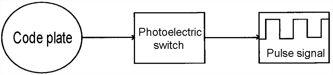
The code plate is integrated with the rotating body and rotated. Photoelectric switch through the photoelectric effect, do the door circuit processing, the output of a high and low level pulse signal. The pulse signal is proportional to the speed. To achieve the physical speed to the conversion of electrical signals.
Specifications
|
Capacity
|
5Nm,10Nm, 20Nm, 50Nm, 100Nm, 200Nm, 500Nm, 1000Nm, 2000Nm, 5000Nm,10KNm, 20KNm, 30KNm, 50KNm, 100KNm, 200KNm, 300KNm, 500KNm(optional)
|
|
Power supply
|
±15V DC(Applicable frequency signal output),
24V DC(Applicable voltage or current signal output)
|
|
Torque signal
|
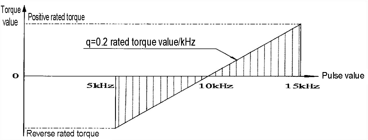
5~15Khz(Amplitude 12V, Zero point 10kHz)、4~20mA、1~5V、0-10V(optional)
|
|
Speed range
|
0~1000、3000、6000、8000rpm
|
|
Speed signal
|
60 Pulse / turn (No accumulation error,Amplitude 12VDC)、4-20mA、1~5V
|
|
Accuracy
|
±0.25%、±0.5%
|
|
Year stability
|
0.3%/year
|
|
Insulation
|
≥200MΩ(100VDC)
|
|
Ambient temperature
|
-20~60℃(Can be customized high temperature type -20~120℃)
|
|
Relative humidity
|
0~90%RH
|
|
Overload
|
150%
|
|
Frequency response
|
1ms
|
Application areas
1. Detection of motor, internal combustion engine and other rotating power equipment, output torque and power;
2. Detection of motor, wind, pump, mixer, reducer, transmission, hoist, propeller, drilling machinery and other equipment load torque and input power;
3. Detection of various machining centers, automatic machine tool work in the process of torque;
4. Detect the torque and efficiency of the various rotating power equipment systems;
5. Detection of torque at the same time can detect speed, shaft power;
6. Can be used to manufacture viscometer, electric, pneumatic, hydraulic torque wrench;
Load characteristics diagram
Installation of dynamic torque sensors
Structural schematic
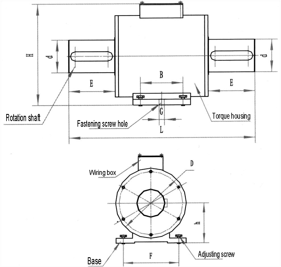
Dimensions
|
N.m
|
D
|
d
|
L
|
E
|
H
|
h
|
B
|
G
|
F
|
Key(L × W × H)
|
Notes
|
|
5-100
|
78
|
18
|
188
|
28
|
111
|
54
|
72
|
10
|
70
|
26×6×6
|
Single key
|
|
200
|
88
|
28
|
207
|
35
|
132
|
60
|
72
|
10
|
70
|
30×8×7
|
Single key
|
|
300-500
|
98
|
38
|
240
|
45
|
142
|
65
|
72
|
10
|
70
|
38×10×8
|
Double key
|
|
1000
|
108
|
48
|
275
|
60
|
152
|
70
|
69
|
11
|
90
|
40×14×9
|
Double key
|
|
2000
|
118
|
55
|
298
|
70
|
164
|
77
|
69
|
12
|
90
|
60×16×10
|
Double key
|
|
3000-5000
|
143
|
75
|
356
|
100
|
189
|
90
|
68
|
14
|
146
|
93×20×12
|
Double key
|
|
10K-20K
|
158
|
98
|
388
|
118
|
204
|
109
|
80
|
14
|
170
|
108×28×16
|
Double key
|
|
30K
|
205
|
125
|
395
|
110
|
270
|
140
|
79
|
17
|
170
|
102×32×18
|
Double key
|
|
50K
|
215
|
140
|
451
|
135
|
273
|
138
|
79
|
17
|
170
|
123×36×20
|
Double key
|
Note: The sizes are just for reference only, please confirm the size when place order!
Installation diagram
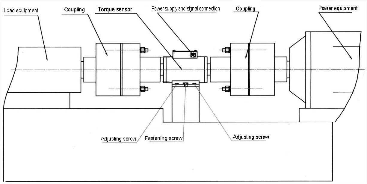
Installation method
1. Measure the shaft diameter and center of the sensor.
2. Use two sets of couplings or flanges to install the sensor between the power equipment and the load.
3. Adjust the center of the power equipment, load, sensor center and coaxial degree, less than 0.01mm, and then fix it, and fasten it reliably, not allowed to loose. When use small range or high speed sensor, to strictly guarantee the center of the connection is high and coaxial. Or may cause measurement errors and damage to the sensor.
4.When connecting ,can use rigid or flexible coupling, when the vibration is large or coaxial can not guarantee the installation requirements (greater than 0.05mm, less than 0.02mm), it is recommended to use a wrap, elastic or universal joint coupling; And between the sensor base and the support frame is recommended to add about 10mm rubber pad to reduce the damage to the sensor when the sensor installed not coaxial.
5. Power source and load equipment must be fixed and reliable to avoid vibration; sensor support base must have a certain strength to ensure the stability of the installation, to avoid causing excessive vibration, or may cause instability in the measurement data, affecting the measurement accuracy.
6. The coupling should be close to the shoulder at both ends of the sensor. Sensors is precision measuring instruments, during installation and use of prohibited impact, beating and other violent impact.
7. The sensor is recommended to use the level of installation, the installation of other angles, please carefully install the sensor,it is not allowed with too large axial and bending moment, otherwise it may affect the use of the sensor, and even cause damage to the sensor.
Commonly used signal types and ancillary products
1. Directly send the torque frequency signal to the computer or PLD for processing;
2. Supporting XSM torque display, direct display torque value;
3. Match the TSW series torque speed power meter directly display torque, speed and power values
4. Supporting F / I or F / V signal conversion module, the frequency signal is converted to 4-20m A or 1-5V and
other commonly used analog signals to facilitate customer signal acquisition.
5. Selection of our company's professional data acquisition card and supporting software to achieve torque, speed and other signal acquisition, storage, printing, playback and other functions.