Model: YGX-TQ804 Non-contact micro rotary torque sensor
Overview
YGX-TQ804 series micro range torque sensor is developed on the basis of the standard torsion strain sensor, which is specially designed to transmit torque parameters. YGX-TQ804 micro range torque sensor in the structure to avoid the interference of the bearing friction torque.
Features:
It can transmit static torque signal, dynamic torque signal, it is unrelated with wether the rotation ,rotation speed and steering when transmiting a signal ,can be adapted a long time, high precision, good stability, small size, light weight, easy installation, it can continuously to transfer the positive and negative torque signal without repeatedly repeating zero.
no collector ring and other wear parts, it can run long time in high speed, strong anti-interference, can be anywhere, installed in any direction.
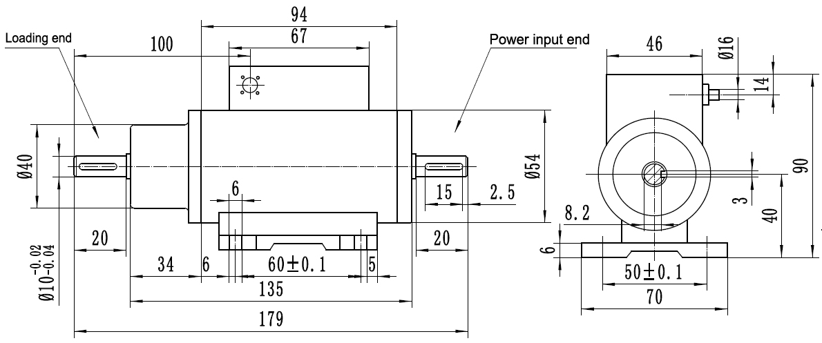
Dimensions(mm):

Specifications
| Range |
0.01~2N.m. |
|
Working voltage
|
±15V DC
|
|
Output
|
5KHz—15KHz |
|
Accuracy
|
0.5%FS |
|
Operation temperature
|
0~50?C
|
|
Frequency response
|
100μs
|
|
Insulation
|
200MΩ(100V)
|
|
Relative humidity
|
90%RH
|
Range calculation and selection:
The formula: M = 9550 × P / n
M: Torque (N.M) P: Power (Kw) n: Speed (r / min)
In the mechanical system with three phase induction motor as the prime mover, the torque range should be selected as 2 ~ 3 times of the rated torque
Installation and use:
1. YGX-TQ804 micro range torque sensor are divided into A and B-side end, B-side for the test side, A side for the auxiliary end, when B side through the coupling and the test equipment is connected to the installation ,must avoid additional bending moment.
2. Because the sensor elastomer is very small, so to strictly limit overload, overload range is≤100%, otherwise easily damaged. To avoid the error of the bending moment caused by the gravity of the coupling, it is recommended to use it as vertically as possible.
3. When transfer the output torque of the motor: the motor output shaft and the sensor transfer terminal connection, connect a DC generator on the auxiliary end of the sensor, at the generator output en connecting a slide wire potentiometer to change the generator load current, then can adjust the output torque of the motor to be measured
4. When measuring load torque resistance: the load device and sensor transmission terminal connected, in the auxiliary end of the sensor connecting corresponding power motor, starting motor,then can transmit the load resistance moment of load equipment
Precautions:
1. The correct wiring required, power supply range: + 15VDC ± 1V.
2. Signal line output shall not be on the ground, the power supply short circuit, the output current is not more than 10mA.
3. Shielded cable shield must be connected to + 15V common terminal (power ground).
4.The 4 sensor elastomer very small, so to strictly limit overload, overload range≤100%, otherwise easily damaged.
5. Radial pulsation shall not be greater than 0.5mm.
6.If you have any questions, please contact with our company, the warranty period is not allowed to disassemble.
7. In dimensions can be seen, the B-side of this sensor is test end, A side is the power end,
are particularly vulnerable to damage due to small scale, we must pay special attention to the installation.
