Dimension (mm):
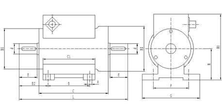
|
Capacity
(N.M)
|
Φ
d
|
Φ
D2
|
A
|
B
|
C
|
E
|
F
|
G
|
H
|
H1
|
C1
|
E2
|
L
|
Key b*h*l*n
|
|
5
|
18
|
78
|
8
|
72
|
122
|
31
|
61
|
100
|
54
|
116
|
90
|
50
|
188
|
6x6x25x1
|
|
10
|
18
|
78
|
8
|
72
|
122
|
31
|
61
|
100
|
54
|
116
|
90
|
50
|
188
|
6x6x25x1
|
|
20
|
18
|
78
|
8
|
72
|
122
|
31
|
61
|
100
|
54
|
116
|
90
|
50
|
188
|
6x6x25x1
|
|
30
|
18
|
78
|
8
|
72
|
122
|
31
|
61
|
100
|
54
|
116
|
90
|
50
|
188
|
6x6x25x1
|
|
50
|
18
|
78
|
8
|
72
|
122
|
31
|
61
|
100
|
54
|
116
|
90
|
50
|
188
|
6x6x25x1
|
|
100
|
18
|
78
|
8
|
72
|
122
|
31
|
61
|
100
|
54
|
116
|
90
|
50
|
188
|
6x6x25x1
|
|
200
|
28
|
92
|
8
|
72
|
123
|
41
|
61
|
100
|
60
|
125
|
90
|
59
|
209
|
8x7x35x1
|
|
500
|
38
|
96
|
8
|
72
|
124
|
55
|
61
|
100
|
65
|
135
|
90
|
74
|
238
|
10x8x50x2
|
|
1k-2k
|
48
|
106
|
12
|
69
|
126
|
70
|
78
|
120
|
68
|
144
|
90
|
90
|
270
|
14x9x65x2
|
|
5000
|
75
|
144
|
12
|
69
|
131
|
105
|
156
|
180
|
90
|
185
|
100
|
139
|
347
|
20x14x95x2
|
|
10000
|
98
|
158
|
14
|
80
|
143
|
118
|
170
|
200
|
110
|
214
|
110
|
155
|
389
|
28x16x115x2
|
|
20k-30k
|
105
|
170
|
14
|
87
|
160
|
125
|
180
|
204
|
115
|
236
|
123
|
165
|
420
|
28x16x119x2
|
|
50k-60k
|
150
|
240
|
14
|
89
|
163
|
123
|
184
|
230
|
153
|
309
|
123
|
165
|
419
|
40x22x115x2
|
|
100k
|
170
|
270
|
16
|
95
|
188
|
200
|
194
|
240
|
169
|
340
|
140
|
252
|
598
|
45x25x195x2
|
Features:
1. Starting 5 minutes to enter the working state, do not need to preheat process.
2. High detection accuracy, good stability, strong anti-interference.
3. No need to repeatedly adjust the positive and negative torque.
4. Small size, light weight, easy to install.
5.Sensor can be separated from the indicator, independent use, directly output frequency signal or analog signal proportional to torque.
Main performance and electrical index:
Torque accuracy:<±0.5% F. S., <± 0.25% F.S., <±0.1% F.S. (optional)
Frequency response: 100 μs
Nonlinear:< ±0.1% F. S.
Repeatability: <±0.1% F. S.
Back difference: < 0.1% F. S.
Zero drift: < 0.2% F. S.
Zero temperature drift: < 0.2% F.S. /10 ℃
Working temperature: - 20 ~ 50℃
Storage temperature: - 40 ~ 70 ℃
Power supply voltage: 15VDC, 24VDC (optional)
Signal output: 5KHz - 15KHz, 0-20mA, 4-20mA, 0-5V, 0-10V, 1-5V, (optional)
The sensor range selection
The selection of the measuring range of the torque sensor should be based on the actual measurement of the maximum torque, under normal circumstances should be left a certain margin, to prevent overloading cause damage to the sensor.
The formula: M = 9550 × P / N
M: Torque Units: N.m.
P: Motor Power Unit: KW
N: Rotation speed Unit: r / min
If you are using a three-phase induction motor, due to the motor starting a large instantaneous torque, the proposed torque range should be selected to 2-3 times the rated torque.
Electrical wiring is defined:
Torque sensor with an aviation connector (with shielded cable), shielded cable lead wire definition:
1. Power supply: ± 15V output: 5-15KHz
Power :( Red + 15V) (Black ground) (Blue - 15V)
Torque output : (Yellow + ) (Black - )
2. Power supply: ± 15V Output: 5-15KHz Built-in speed sensor
Power :( Red + 15V) (Black ground) (Blue - 15V)
Torque output : (Yellow + ) (Black - )
Speed output: (White +) (Black -)
3. Power supply: ± 15V Output: 4-20mA (analog)
Power :( Red + 15V) (Black ground) (Blue - 15V)
Output : (Yellow +) (White - )
4. Power supply: ± 15V Output: 4-20mA (analog) Built-in speed sensor
Power :( Red + 15V) (Black ground) (Blue - 15V)
Torque output :(Yellow +) (Green -)
Speed output: ( White +) (Gray -)
5. Power supply: 24V Output: 5-15KHz
Power :( Red 24V) (Black ground)
Torque output: (Yellow +) (Blue -)
6. Power supply: 24V Output: 5-15KHz Built-in speed sensor
Power :( Red 24V) (Black ground)
Torque output: (Yellow +) (Blue -)
Speed output: (White +) (Blue -)
7. Power supply: 24V Output: 4-20mA (analog)
Power :( red 24V), (Black ground)
Torque output :( Yellow +), (Blue -)
8. Power supply: 24V Output: 4-20mA (analog) Built-in speed sensor
Power :( Red 24V) (Black ground)
Torque output :(Yellow +) (Green -)
Speed output: ( White +) (Gray -)
Note:
If there is frequency converter or servo motor, please add 1:1 isolation transformer in the power supply of the sensor, the sensor cable shield connect to the ground; if the sensor has a matching indicator, the indicator also need to add 1:1 isolation transformer.
Installation:
1.Installations: Horizontal and vertical installation.
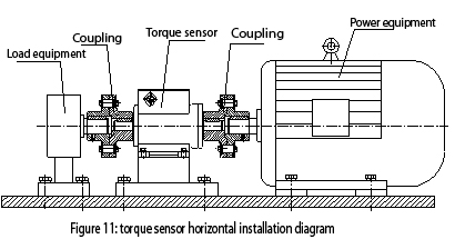
(1) Horizontal installation: as shown in figure 11:
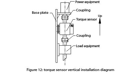
(2) Vertical installation: as shown in figure 12:
2. Connection:
The connection between the torque sensor and the power equipment and the load device
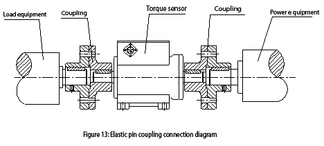
(1) Elastic pin coupling connection as shown in Figure 13, this connection is simple in structure, easy to process and easy to maintain. It can micro compensate the relative offset of the shaft caused by the installation error of the trace , can also play a minor role in reducing the vibration. Suitable for medium load and high speed operation frequent starting situations, the working temperature is -10-50℃.
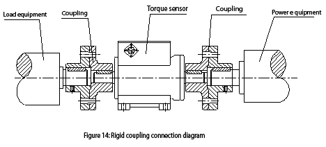
(2) Rigid coupling connection: As shown in Figure 14, this connection in the form of simple structure, low cost, no compensation performance, can not buffer damping, high mounting accuracy of the two axes. For low vibration working conditions.
3. Installation requirements:
(1) The torque sensor can be installed horizontally, and can also be installed vertically.
(2) As shown in Figure 11, 12, power equipment, torque sensor, load equipment should be installed on a stable and solid basis, in order to avoid excessive vibration, otherwise it may occur data instability, reduced accuracy, or even damage the sensor.
(3) Adopt a elastic pin coupling or rigid coupling connection.
(4) Power equipment,torque sensor, load equipment, the concentric degree of axis should be less than Φ0.05mm.
4. The installation interface shape and size reference:
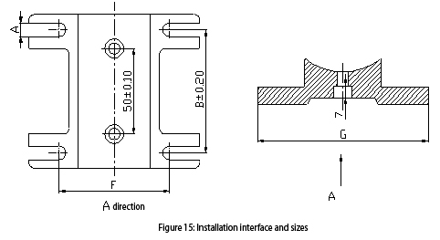
As shown in Figure 15: the value of the figure marked A, F, B, G are shown in Figure 7 correspond to the specifications table.
5. Installation steps:
(1) According to the connection form of the shaft and the length of the torque sensor to determine the distance between motor and load equipment, adjust the distance between the base plane and the axis of the motor and the load equipment,so that their their axes the coaxial degree is less than Φ0.03mm,fixed the motor and load equipment on the base plane.
(2) The couplings are respectively mounted on the respective shafts.
(3)Adjusting the distance between the torque sensor and the base plane,make coaxial degree of the axis of the sensor shaft and the motor and the load equipment is less than Φ0.03mm,fix the torque sensor and load equipment on base plane.
(4) Fastening the couplings, the installation is complete.
